
An Introduction to
ETHERNET/IP
What is EtherNet/IP?
EtherNet/IP is an open industrial communication standard designed to deliver the Common Industrial Protocol (CIP) application layer over traditional IEEE802.3 Ethernet networks. By leveraging standard Internet Protocol (IP) alongside TCP and UDP transport layers, EtherNet/IP provides fast, practically deterministic and scalable communication across complex automation environments.
It has gained global acceptance because it utilizes the exact same physical infrastructure and software framework found in standard commercial IT applications and is supported by the world’s leading control manufacturers.


Table of Contents
Ethernet vs. EtherNet/IP
Most people who work in an office associate the term “Ethernet” with the physical cable behind their desk that connects their office PC to a local printer, a corporate server, or the Internet. This cable is only the physical part of Ethernet. On that commercial wire sits a standard suite of office protocols like HTTP for web browsing or SMTP for email. These work well in office environments, but lack the mechanics required for machine automation.
EtherNet/IP is a specialized industrial application protocol that adapts standard Ethernet to meet the demands of the factory floor, like accessing data and communicating in real time (or very close to it).
| Feature/Demand | Standard Commercial Ethernet (Office IT) | Industrial EtherNet/IP (Factory Floor OT) |
|---|---|---|
| Primary Role | File sharing, internet access and corporate communication | Accessing real-time data embedded in drive systems, operator workstations and I/O blocks |
| Timing | Time-Insensitive: Users can wait for webpages or emails to load without consequence | Practical Determinism: Devices must operate in real-time (or very close to it) with sub-millisecond precision |
| Data Payload | Large, sporadic blocks of data | Small, continuous streams of data at high frequency |
| Network Infrastructure | Standard unmanaged switches, corporate routers and unshielded cabling | Industrial-grade managed switches, Layer 3 isolation routers and ruggedized shielded cabling |
Traditionally, Ethernet faced limited acceptance in industrial automation due to high hardware costs, a lack of intelligent switches and routers and the market dominance of proprietary vendor fieldbuses.
Today, the ubiquity of high-speed Ethernet hardware, powerful PCs and smart switching has made Ethernet the most common network standard for modern industrial automation.
The EtherNet/IP Stack: How EtherNet/IP Works
EtherNet/IP can be thought of as having multiple layers working together. Unlike proprietary industrial networks that invent their own hardware transport mechanisms (e.g., EtherCAT or PROFINET IRT), EtherNet/IP relies entirely on standard commercial Ethernet infrastructure.
While the ODVA documentation describes EtherNet/IP using the 7-layer OSI model, when applied to a practical, real-world EtherNet/IP architecture, the protocol stack collapses into the 4-layer TCP/IP model which will be used throughout this document. To understand why the automation world treats these frameworks differently, you can read our full breakdown on the differences between the OSI and TCP/IP models.
When applied to EtherNet/IP, the TCP/IP model breaks down as follows:
- CIP (Application layer)
- TCP/IP and UDP (Transport layer)
- IP (Internet layer)
- Network hardware (Network Access layer)

The Application Layer: An Overview of CIP
Common Industrial Protocol (CIP) is a network-independent, application-layer protocol that provides a suite of network functionality designed to establish unified data representation, connection management and messaging, enabling seamless interoperability between devices from multiple vendors.
CIP provides three core functions:
- Unified, Object-based Data Representation: Data and functions inside CIP devices are presented as objects with well-defined attributes, services and behaviors, enabling a single driver to communicate across entirely different devices.
- Connection Management: CIP establishes dedicated data pipelines between controllers and devices, predefining network parameters to ensure a predictable data flow and reliable fault detection.
- Vendor Interoperability: By utilizing standardized object data structures, system integrators can use CIP-enabled hardware from different manufacturers without the need for custom drivers.
Because CIP is completely media-independent, it serves as the universal upper-layer language for an entire family of networks:
- CIP on Ethernet technology = EtherNet/IP
- CIP on CAN technology = DeviceNet
- CIP on CTDMA technology = ControlNet
- CIP on TDMA technology = CompoNet
The Transport Layer: TCP/UDP Protocols and EtherNet/IP Ports
At the Transport layer, CIP messages are encapsulated into an Ethernet message and sent across the network using either Transmission Control Protocol (TCP) or User Datagram Protocol (UDP), utilizing specific registered destination port numbers.
Depending on the operational priority of the data, EtherNet/IP routes traffic across two distinct pathways:
- Explicit Messaging (TCP Port 44818): Used for non-time-critical data like configuration, troubleshooting and uploading programming logic. Because it uses TCP, it establishes a formal connection handshake and includes strict error checking to guarantee accurate delivery.
- Implicit Messaging (UDP Port 2222): Used to stream real-time, time-critical I/O data from field devices directly to controllers. By using UDP, the network bypasses the processing overhead of TCP, prioritizing raw speed and determinism over delivery verification.
The Internet Layer: Internet Protocol (IP)
The Internet layer is responsible for addressing and routing packets across the network. Because EtherNet/IP uses standard Internet Protocol (IP), it treats every industrial device like a standard network node.
However, routing must be carefully managed via routers and managed switches to maintain strict separation between factory floor control traffic and the rest of the enterprise network.
The Network Access Layer: Ethernet Frames, Hardware and Topologies
EtherNet/IP uses standard IEEE 802.3 Ethernet technology to define its physical media, frame format and media access rules. Using the TCP/IP model, this layer is comprised of the Data Link and Physical layers of the OSI model.
Data Link Layer
The Data Link layer is responsible for moving frames between devices across the local network. It relies on the Media Access Control (MAC) protocol to dictate how devices share the physical wire.
- MAC Addressing: Identifies the unique source node sending the frame and the destination node receiving the data.
- Multicast Addressing: Allows a single implicit I/O message to be sent to multiple destination nodes simultaneously.
- Full-duplex Ethernet: Allows networked devices to send and receive data at the same time, eliminating data collisions and providing the high throughput required for automation.
Physical Layer
Because the physical layer uses standard commercial Ethernet standards, EtherNet/IP networks can use standard commercial copper wire (Cat5e or later) or fiber optic cabling. To withstand harsh factory environments, EtherNet/IP deployments utilize ruggedized hardware including heavily shielded twisted pair cables or sealed connectors with an IP67 rating.
EtherNet/IP Network Topologies
EtherNet/IP networks can accommodate a virtually unlimited number of nodes and a variety of topologies:
- Star Topology: In a star topology, all network devices are individually connected to a central switch, which is then connected to a higher-level network access point. Star topology is one of the most prevalent topologies used in control networks.
- Linear Segments: Devices in linear networks feature embedded three-port switches, allowing engineers to wire Ethernet-enabled devices in a daisy chain, exactly like RS-485 serial networks.
- Ring Topology and Device Level Ring (DLR): In a ring topology, devices are daisy chained together in a ring, allowing messages to travel in either direction. Utilizing the Device Level Ring (DLR) protocol, EtherNet/IP networks can detect failures and quickly change to function as 2 linear segments.
- Hybrid Topology: Some manufacturers choose to combine two or more topologies within a single EtherNet/IP network, taking advantage of different technologies. However, this adds complexity and can be more difficult to maintain.
EtherNet/IP Communication Model
EtherNet/IP uses two different communication models depending on the operational priority of the data being transmitted.
Implicit Messaging: The Producer-Consumer Model
Implicit messaging relies on a producer-consumer relationship to move real-time I/O data. In this model, a producer publishes its data onto the network once, and any number of consumers can simultaneously listen to and “consume” the exact same data.
Instead of a PLC constantly polling a device, a formal connection contract is established up front, including instructions for when the connection will break.
Explicit Messaging: The Request-Response Model
Explicit messaging handles non-time-critical data using a traditional, point-to-point request-response relationship. In this model, data is only transmitted when a device explicitly asks for it.
While these transactions can be handled as one-off unconnected messages, EtherNet/IP often establishes dedicated Explicit Connections (Class 3) to manage ongoing, non-real-time data exchanges between specific devices.
EtherNet/IP Devices: Scanners vs. Adapters
- Scanner: Typically a high-level controller such as a PLC. Scanners initiate connections, dictate transmission speeds, send outputs and gather inputs. The term “Scanner” is functionally synonymous with the “Master” or “Client” terminology of older protocols.
- Adapter: Typically peripheral field devices such as sensors, VFDs or I/O blocks. Adapters wait for incoming connection requests from Scanners, execute the commanded tasks and return their I/O data. The term “Adapter” is functionally synonymous with “Slave” or “Server” terminology of other protocols.
- EtherNet/IP Gateways: In modern industrial networks, EtherNet/IP gateways can act as an Adapter or Scanner, or both simultaneously. Its primary role is to translate data between EtherNet/IP networks and devices that natively speak other protocols without requiring custom logic or expensive in-rack modules.
It is important to note that, at times, a high-level device like a PLC can act as both a Scanner and Adapter depending on who initiates the connection. For example, if a PC-based configuration tool (acting as a Scanner) sends an explicit request to a PLC, the PLC temporarily acts as an Adapter to accept and respond to that message, even while it actively maintains its own Scanner connections to downstream field devices.
EtherNet/IP Data Representation: An Overview of the CIP Object Model
EtherNet/IP adapts CIP to run over a standard Ethernet architecture, utilizing an object-oriented database model to represent data instead of the numbered registers and coils found in legacy fieldbuses.
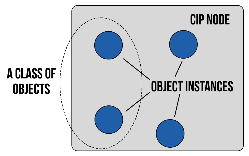
In the CIP object model, every piece of data, configuration setting and diagnostic function inside a device is represented as a structured collection of objects. These objects are broken down into classes, instances and attributes:
- Class: A set of objects that represents the generic type of system component or functional group.
- Example: An AC/DC Drive Object Class serves as a template for managing motor parameters inside a VFD.
- Instance: The actual representation of a particular object within a class. Each instance copies the exact structure of the parent class but represents a separate physical or logical entity.
- Example: A controller generates a distinct instance of the AC/DC Drive Class for each motor it controls: Instance 1 (Motor A) and Instance 2 (Motor B)
- Attribute: A specific characteristic, runtime variable or data point belonging to an object instance. While each instance shares the same attributes, each maintains its own unique, independent attribute value.
- Example: Within Instance 1 (Motor A), the Actual Output Current attribute has a value of 4.2A. Meanwhile in Instance 2 (Motor B), the Actual Output Current attribute is 0.0A because it is currently stopped.
Network-Specific EtherNet/IP Objects
While CIP is network-independent, it uses specific network layer objects to manage the physical and logical connections unique to Ethernet networks.
- TCP/IP Interface Object: Configures and reports the device’s IP network settings. Critical attributes include the IP Address, Subnet Mask, Gateway Address, Configuration Method and Host Name.
- Ethernet Link Object: Maintains the physical Ethernet interface status and performance metrics. Critical attributes include the Interface Speed, Duplex Mode, Media Counters, Interface Control and MAC Address.
CIP Object Library
The CIP protocol contains a large collection of commonly defined objects, ensuring seamless interoperability between hardware from different manufacturers. Because this library is standardized across the entire automation industry, an EtherNet/IP Scanner doesn’t need a unique, custom-written software driver for every brand of device on the network. CIP-compliant devices can communicate right out of the box.
Vendor-Specific Objects and Electronic Data Sheets
Device developers are not limited to the objects contained in the published CIP specifications. Vendors are free to define custom, vendor-specific objects to expose unique pieces of information or specialized functions in their hardware.
To make these custom parameters accessible to the rest of the network, vendor-specific objects are outlined in an electronic data sheet (EDS) file. These standardized text files describe all the device-specific objects and parameters. When an EDS file is uploaded into a PLC’s configuration software, it creates the underlying tags and memory structures required to support the custom object.
EtherNet/IP Frame Structure
An EtherNet/IP frame encapsulates a CIP data payload within standard TCP/IP (or UDP/IP) packets, which are then carried inside a standard Ethernet frame as defined by the IEEE 802.3 standard. In this structure, each network layer adds its own tracking information around industrial data.
To understand how this works, the sections below break down the frame from the inside out, starting at the data payload and moving outward through each protective network layer.
The Industrial Application Layer
This layer defines the core industrial payload containing the actual automation logic, object definitions and commands. It adds the mandatory EtherNet/IP formatting around raw data tags so that different industrial devices can interpret the message. The EtherNet/IP telegram includes:
- EtherNet/IP Encapsulation Header (24 bytes): Manages the communication session, defines the command type and tracks message status between devices.
- CIP Payload (Variable, up to 1500 bytes under standard Ethernet MTU): The CIP data that contains the actual commands
The Transport Layer
This layer wraps the telegram into a transport protocol header, using specific destination port numbers to dictate how fast and how reliably the data must move.
- TCP/UDP Header (8 to 20 bytes): Manages the transport-layer connection, using the specific port numbers (44818 for TCP, 2222 for UDP) to route data to the correct software application.
The Network Routing Layer
This layer encapsulates the transport segment inside an internet packet, adding standard logical network tracking so the message can route successfully between different corporate or plant-floor subnets.
- Internet Protocol (IP) Header (Typically 20 bytes): Handles network-layer routing by containing the source and destination IP addresses
The Physical Ethernet Link Layer
This layer adds the physical hardware address to the front and a mathematical verification check to the absolute end.
- Physical Frame Header
- Preamble (7 bytes): Synchronizes the receiver’s clock with incoming data
- Start Frame Delimiter (1 byte): Signals the beginning of the frame payload
- Destination Address (6 bytes): Specifies the MAC address of the device to which the frame is being sent
- Source Address (6 bytes): Specifies the MAC address of the device sending the frame
- EtherType/Length (2 bytes): Identifies the specific network layer protocol being carried inside the payload or indicates the total size of the data payload
- Physical Frame Footer
- Frame Check Sequence (FCS) (4 bytes): Appended to the end of the frame. Holds a cyclic redundancy check (CRC) value that detects transmission errors.
Advantages to EtherNet/IP
The advantages of the CIP protocol layer over Ethernet are numerous.
- Consistent device access means that a single configuration tool can configure CIP devices on different networks from a single access point without using vendor-specific software.
- Classifying all devices as objects reduces the training and startup time needed when new devices come online.
- The Ethernet physical layer provides improved response time and greater data throughput than DeviceNet and ControlNet.
- EtherNet/IP links devices from the sensor bus level to the control level to the enterprise level with a consistent application layer interface.
User Challenges of EtherNet/IP
EtherNet/IP protocol implementation is not without challenges. Two of the most important challenges to the first-time user include training and network configuration.
Collaboration between IT and OT
One common problem is the lack of trained staff who understand both IT fundamentals and automation networks. Successfully implementing the EtherNet/IP protocol requires a collaborative effort between IT and automation staff.
Network Configuration
A second challenge is proper network configuration. Planning your Ethernet factory automation infrastructure is essential. Careful identification of all your control loops, choosing the correct routers, switches and paths and documenting your network properly are requisites for a communications network that meets your production goals and requires little ongoing maintenance.
Perceived Lack of Determinism
Detractors of Ethernet applications on the factory floor often cite the lack of inherent determinism in Ethernet communications protocol to keep it out of automation applications. While true in the past when networks relied on half-duplex hubs and CSMA/CD, advancements in intelligent switches have largely eliminated this argument.
These switches utilize full-duplex communication to create separate collision domains, completely bypassing CSMA/CD overhead to offer the determinism required of almost all but the most demanding of automation applications.
EtherNet/IP Protocol Governance and the ODVA
Today, EtherNet/IP is managed solely by ODVA, which is responsible for:
- Publishing the EtherNet/IP specification to maintain universal technical standards
- Overseeing the enhancement process to safely integrate new features like CIP Safety and CIP Security
- Licensing EtherNet/IP technology to vendors that manufacture or sell compliant hardware
- Promoting awareness of EtherNet/IP and driving global adoption
- Ensuring product compliance through rigorous, mandatory conformance testing and official conformity reporting
EtherNet/IP Conformance
Any product utilizing the open CIP protocol, including EtherNet/IP, must go through conformance testing to verify it complies with the official protocol standard, ensuring interoperability in multi-vendor systems. Conformance testing is run and administered by ODVA at its designated test facilities.
ODVA conformance testing is broken down into four parts:
- Protocol Test: A software validation test that systematically verifies that standard CIP objects, instances, attributes and services behave as described in the EtherNet/IP specification.
- Physical Layer Test: A hardware inspection test that verifies connector specifications, indicator LEDs and electronic isolation.
- Interoperability Test: A practical application test where a product is stress-tested on a live network.
- Device Description File Check: Validation of the device’s EDS file and software mapping.
Upon successful completion of conformance testing, vendors receive an official Declaration of Conformity from ODVA. This certification allows EtherNet/IP products to go to market and assures the industry that products are built to strict ODVA specifications.
RTA EtherNet/IP Conformance Testing Support

For device manufacturers, writing EtherNet/IP stacks from scratch adds high engineering overhead, months of development time and can make certification uncertain. To ensure OEMs pass rigorous ODVA conformance testing on the very first try, RTA offers comprehensive pre-conformance support for devices built using the RTConnect Module.
The RTConnect Module service package includes:
- A dedicated Enginerd to be your protocol partner
- Data modeling including documentation and communication files
- RTA lab testing, providing you with test results you need to present at the conformance lab
A Brief History of the EtherNet/IP Protocol
The EtherNet/IP protocol was originally developed in the late 1990s through a joint effort by Allen-Bradley and ODVA. Prior to its introduction, industrial networking was restricted by proprietary vendor protocols and the limitations of legacy protocols like DH+ and Modbus RTU.
To solve this, manufacturers were already successfully deploying CIP over older, specialized fieldbuses like ControlNet (CIP over CTDMA technology) and DeviceNet (CIP over CAN). However, while the factory floor was adopting these early open networks, standard commercial Ethernet took off in the enterprise. Migrating the CIP protocol to Ethernet was simply the next logical evolutionary step.
RTA’s Place in EtherNet/IP History
RTA provided the EtherNet/IP source code for the very first ODVA-certified device – a SICK barcode scanner that successfully completed conformance testing on January 16, 2002. Today, RTA continues to serve the automation market with EtherNet/IP protocol gateways and source code stacks


