

An Introduction to
MODBUS TCP/IP
What is Modbus TCP/IP?
Modbus TCP/IP is the evolution of the Modbus RTU protocol, adapted for modern Ethernet networks. By embedding the Modbus messaging structure inside a TCP/IP packet, it allows industrial devices like PLCs, I/O modules and Modbus gateways to communicate over Ethernet-based intranet or internet networks.
As variant of the Modbus family of simple, vendor-neutral protocols, Modbus TCP/IP has become the de facto automation standard. Modbus TCP/IP is sometimes referred to as the Modbus TCP protocol or just Modbus TCP.


Table of Contents
Modbus TCP/IP Communication Model
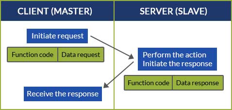
Modbus TCP/IP operates on a client/server architecture with request-response communication, where a client (master) sends requests to server (slave) devices to read or write data, and the server performs the action and responds back to the client.
Modbus TCP/IP Addressing
In the Modbus TCP/IP client/server model, the physical node addresses (server IDs) used in serial networks are replaced by a combination of an IP (Internet protocol) address and an optional Unit ID. This allows a client to route commands to specific devices by first targeting a unique IP address on the Ethernet network and then specifying a particular server, through a Unit ID, once the data arrives.
Depending on the network setup, the Unit ID serves two distinct purposes: ensuring protocol compliance and routing to serial devices.
Direct Connections
When directly connecting Ethernet-native devices, the IP address already provides a unique, direct path between them, making the Unit ID redundant because there is only device at each location.
In practice, the Unit ID is typically set to 0 or 255 to ensure compliance with the Modbus TCP/IP specification. Using these reserved values ensures the message is processed by the main controller’s application layer rather than being discarded or misinterpreted as an invalid sub-network address.
Most modern Ethernet-native servers are programmed to ignore the Unit ID entirely but setting it to 255 remains the industry-standard safe value for direct communication.
Modbus Gateways
The Unit ID becomes critical when connecting to a Modbus TCP/IP gateway, which acts as a translator between a multi-device serial network and Modbus TCP/IP.
In this scenario, the gateway is assigned a single IP address that represents the entire serial chain. To target a specific device, the client uses Unit IDs 1 to 247. This allows each serial server to be individually represented and polled through the same Ethernet connection, using the Unit ID to uniquely identify the destination once the packet reaches the gateway.
Modbus TCP/IP Polling
In any Modbus network, clients must request, or poll, servers for updates. In traditional RS-485 serial networks, the client must poll servers sequentially, waiting for a response from one device before moving to the next to avoid data collision on the single wire.
Modbus TCP/IP utilizes high-speed Ethernet switches and TCP sockets to allow for simultaneous communication. A socket is a unique software connection established between the client’s IP and the server’s IP on a specific port. By opening multiple sockets at once, a client can poll several different IP addresses at once rather than waiting for each device in a row.
While the TCP/IP stack allows for multiple concurrent connections, every server has a physical hardware limit on how many simultaneous sockets it can maintain. While a high-end PLC may support 16 or more connections, smaller devices like VFDs or smart sensors may only support 1 or 2. If a client attempts to open more sockets than the hardware supports, the server will reject the connection.
Because the Modbus protocol itself operates on a request-response basis, every command sent by the client must have a corresponding response from the server to confirm the transaction regardless of how many sockets are open.
Polling through a Modbus Gateway
While a client can poll multiple gateways simultaneously, the devices behind a single gateway must still be polled sequentially. Because the gateway must translate the Ethernet message back into a serial broadcast, the RS-485 daisy chain still uses half-duplex (one- at-a-time) communication. If a client sends multiple requests to different Unit IDs on the same gateway too quickly, the gateway will buffer those requests and send them out one by one.
Common Modbus TCP Networking Hardware and Devices
Ethernet Networking Hardware
These devices handle the physical movement of Modbus packets across the factory floor.
- Ethernet Cabling: Ethernet cabling is used to connect each node on the network, whether it is a PLC, switch, gateway, server or other Ethernet-enabled device in the OT or IT network.
- Industrial Ethernet Switches: A switch acts as a traffic cop, directing Modbus packets specifically to the IP address of the target server. This prevents the data collisions common in serial networks and allows multiple clients and servers to talk at once.
- Routers and Firewalls: Routers manage traffic between different network segments, called subnets. They use the IP Address to decide if a packet should stay in the local subnet or move to a different one. Firewalls add security by inspecting a packet’s intended port number (Registered Port 502 for Moddbus TCP/IP), IP address and command.
Ethernet-Native Devices
These are the endpoints of the network that have their own Network Interface Card (NIC) and IP address.
- Client (Master): Typically, a high-level controller such as a PLC or a supervisory computer running SCADA software. The client initiates communication by opening sockets to multiple servers.
- Server (Slave): Ethernet-enabled peripheral devices such as smart sensors, VFDs or I/O blocks, each with their own IP address.
Legacy Devices and Gateways
These components allow the modern Ethernet network to communicate with older serial installations.
- Modbus Gateways: Protocol translator hardware that sits on the Ethernet network with its own IP address and provides one or more serial ports (RS-485) to talk to legacy hardware.
- Serial Server (Sub-device): Older sensors or meters located “beyond” the gateway. They lack an IP address and rely entirely on the gateway and their Unit ID to be seen by the client.
Modbus TCP/IP Physical and Network Layers
Modbus TCP/IP Physical Layer
The number of devices allowed on a Modbus TCP/IP network, the distance data can travel and the speed of communication are determined by the Ethernet physical layer and the network infrastructure. Unlike serial networks limited by electrical interference, Modbus TCP/ip relies on standard IT networking principles.
While other physical layers like fiber optic cabling are used in environments with high electrical interference, this article’s focus is on Ethernet as the primary physical layer.
Cat5e and Cat6 Cable

Modbus TCP/IP utilizes Category 5e or Category 6 (Cat5e/Cat6) shielded Ethernet cables. This physical media is designed for high speed, multi-point connections over a moderate distance (328 feet), which can be extended via switches and repeaters.
While serial networks like RS-485 are limited to 32 devices per segment, a Modbus TCP/IP network is virtually unlimited and only restricted by the number of servers as the IP address scheme allows (typically 254 per subnet). By using routers and switches, these networks can scale to include thousands of devices across an entire facility.
Modbus TCP/IP typically operates at speeds of 100 Mbps or 1 Gbps. This is significantly faster than the maximum 115.2 kbps of serial RTU, allowing for much denser data collection and faster refresh rates for HMI and SCADA systems.
Modbus TCP/IP Network Topology

Unlike the daisy chain required by RS-485 networks, Modbus TCP uses a star topology. In this architecture, every device connects back to a central Ethernet switch meaning that if one cable is damaged, only that specific device goes offline, whereas a break in a serial daisy chain can take down the entire network.
Modbus TCP/IP Network Layers
The network layers define how Modbus data is addressed and delivered over Ethernet. Modbus TCP/IP operates by nesting Modbus instructions inside two standard IT networking protocols: IP and TCP.
The Internet Protocol (IP) Layer
The Internet Protocol (IP) layer is responsible for routing the data packet to its physical destination. Unlike a serial network, where you are limited to devices physically wired to your controller, the IP layer allows a Modbus TCP/IP client to communicate with a server located anywhere on a local or wide-area network. This is achieved through standard IP addressing and subnets, and the Unit ID in the application layer.
The Transmission Control Protocol (TCP) Layer
While the IP layer finds the device, the TCP layer ensures the message arrives intact, accurate and in the correct order.
Modbus TCP/IP establishes a formal handshake between the client and server. This creates a stateful connection where the network stack automatically handles re-transmissions if a packet is lost due to congestion or interference.
Compare this to Modbus RTU, where a client sends a stateless broadcast and waits for a response (or not). If CRC error-checking fails or no response is received within the preconfigured timeout, the message is discarded.
Port 502
Modbus TCP/IP is assigned to Registered Port 502 by the Internet Assigned Numbers Authority (IANA). Using Port 502 ensures Modbus traffic is prioritized and recognizable by network analyzer tools. It also allows industrial firewalls to perform Deep Packet Inspection (DPI) to ensure that packets contain valid Modbus headers and function codes.
Modbus TCP/IP Data Representation
| Modbus TCP/IP Data Type | Common Name | Starting Address |
| Coils | Read/Write bits, binary values, flags | 000001 |
| Digital Inputs | Read Only bits, binary values, flags | 100001 |
| Input Registers | Read Only 16-Bit value | 300001 |
| Holding Registers | Read/Write 16-Bit value | 400001 |
Modbus TCP/IP uses the standard Modbus data representation, where data is organized into two primary formats: coils and registers.
Coils
Coils are simply single bits. The bits can be ON (1) or OFF (0). Some coils represent inputs, meaning they contain the status of some physical discrete input. Others may represent outputs, meaning that they hold the state of some physical discrete output signal.
Registers
Registers are simply 16-bit memory locations and can have a value from 0 to 65535 (0 to FFFF hexadecimal) if unsigned, or -32768 to 32767 if signed. There is no representation for real data like 200.125. To handle “real” data like decimals or larger numbers, modern systems simply combine two consecutive 16-bit registers to create a 32-bit Floating Point or Long Integer.
Registers are grouped into two types based on their function and access permissions: input registers and holding registers.
Input Registers
Input Registers (and their single-bit equivalents, Discrete Inputs) are read-only. A client can request their values but cannot write to them.
Like Discrete Inputs, Input Registers report the state of some external input as a value between 0 and 65535, if unsigned. The original intent of an Input Register was to reflect the value of some analog input — a digital representation of an analog signal like a voltage or a current.
Holding Registers
Holding Registers (and their single-bit equivalents, Coils) are read/write. A client can both request their current values and write new values to them.
Holding Registers were originally designed as temporary program storage for devices like controllers, while Coils represented physical discrete outputs that could be turned on or off. Today, both serve as the primary means of sending commands and configuration data to a Modbus device.
In practice, since most modern Modbus devices are not pure I/O devices, the distinction between Input Registers and Holding Registers has blurred. Many devices expose all of their data through Holding Registers alone. However, understanding the read-only versus read/write distinction remains important when working from a device’s Modbus map.
Modbus TCP/IP Frame Structure
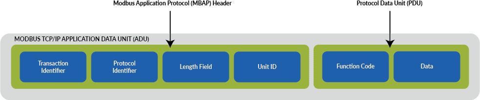
Because Ethernet communication is asynchronous and handled by network switches, a Modbus TCP/IP Application Data Unit (ADU) relies on a dedicated header rather than the precise timing and “dead time” intervals used in serial networks. This connection-oriented, structured frame consists of two parts: an MBAP Header and a Protocol Data Unit (PDU).
The MBAP Header
The Modbus Application Protocol (MBAP) header is a 7-byte dedicated prefix that identifies the Modbus message within the TCP/IP packet. It contains four components:
- Transaction Identifier (2 bytes): Allows a client to send multiple requests at once and correctly match the incoming responses.
- Protocol Identifier (2 bytes): Set to 0 for Modbus.
- Length (2 bytes): A byte count of the remaining fields including the Unit ID, function code and data.
- Unit Identifier (1 byte): Bridges serial and TCP/IP networks by identifying target devices on a serial network.
The Protocol Data Unit (PDU)
The Protocol Data Unit contains the core instruction of the message and is identical to the data used in Modbus RTU. The PDU contains two parts: function codes and data fields.
Function Codes
Function codes tell servers which coil or register to access and whether to read or write to it. The Function Code field is encoded into one byte, with valid codes ranging from 1 to 255. Codes from 128 to 255 are reserved for the exception responses.
Each function code corresponds to specific operations:
- Read function codes allow clients to request data from servers. Common read function codes include:
- 01 – Read coils
- 02 – Read discrete inputs
- 03 – Read holding registers
- 04 – Read input registers
- Write function codes allow clients to send data to servers. Common write function codes include:
- 05 – Write single coil
- 06 – Write single holding register
- 15 – Write multiple coils
- 16 – Write multiple holding registers
To define multiple actions, some functions will have sub-function codes added to them. For instance, the client can read the On/Off states of a group of discreet outputs or inputs. It could also read/write the data contents of a group of registers.
When the client receives the server response, the function code field is used by the server to indicate either an error-free response or an exception response. The server echoes to the request of the initial function code in the case of a normal response.
Data Field
The data field is the payload of the message. It contains the specific details required to execute a Function Code. In a standard client request, the data field is comprised of two primary components:
- A starting address which identifies the first coil or register the client wants to access
- A quantity that identifies the total number of consecutive coils or registers to be processed
For write commands, the data field expands to include the value to be written to the server’s memory.
The structure of the data field changes based on the direction of the communication and the specific task:
- Client commands specify the starting address and the quantity of coils or registers to be retrieved or written. Write commands also contain the values to be sent to the server.
- Server responses contain the incoming byte count followed by the actual values requested or confirmation that the data was written successfully.
Starting Address
Starting addresses identify the first coil or register the client wants to access. There is a critical distinction between how the starting address is identified in device documentation versus how it is addressed in the Modbus TCP/IP message frame.
Register Numbers (Documentation)
Documentation uses human-readable register numbers to categorize data. The first digit acts as a prefix to identify the data table:
- 0xxxxx: Coils (000001 – 065536)
- 1xxxxx: Discrete inputs (100001 – 165536)
- 3xxxxx: Input registers (300001 – 365536)
- 4xxxxx: Holding registers (400001 – 465536)
Data Addresses (Modbus Protocol)
The Modbus protocol itself relies on the Function Code to select the correct table and a 16-bit data address to find the specific location within that table. The addresses are sent in the message as hexadecimal values.
Offsets
An offset is used to mathematically bridge device documentation and the protocol encoding. Because Modbus addresses start at 0, the first register in any table is always addressed as 0000 in the message frame. To translate a register number to a data address, subtract the table’s starting offset.
- Coil offset – 000001
- Discrete input offset – 100001
- Input register offset – 300001
- Holding register offset – 400001
Subtracting these offsets effectively removes the table prefix and shifts the range to start at 0. For example, if you want to read holding register 400108:
- The prefix “4” tells the client to use Function Code 03 (Read Holding Register)
- Subtract the offset to get the protocol address: 400108 – 400001 = 107
- The data address sent in the message frame is 107, or 0x006B in Hex
Quantities
The quantity value makes the client/server model efficient by specifying the number of locations to be read or written in a single request. For example, rather than sending five separate requests for five different values, a client can request a starting address with a quantity of five to retrieve all data in a single transmission.
Error-Checking
Note that the Modbus TCP/IP ADU does not contain the Cyclic Redundancy Check (CRC) bits of the Modbus RTU message. In Modbus TCP/IP, the underlying TCP/IP and Ethernet layers have their own robust error-checking mechanisms, so the 16-bit CRC used in serial communication is redundant and stripped away.
Modbus TCP/IP Data Encoding
Modbus TCP/IP uses a binary representation that mirrors the RTU format. Each byte is coded as an 8-bit binary value (Hex 0-9 and A-F) and transmitted in a raw, continuous stream within the standard Ethernet frame.
Little-Endian Binary Format (Bit Level)
At the bit level, the network hardware handles data in Little-Endian order, meaning the Least Significant Bit (LSB) is sent and received first. The TCP/IP stack manages the timing and synchronization, removing the need for the 11-bit character framing used in serial communication.
Big-Endian Binary Format (Byte Level)
At the byte level, Modbus uses a Big-Endian representation for addresses and data items. This means that when a numerical quantity larger than a single byte is transmitted, the Most Significant Byte (MSB) is sent first.
As shown in the following examples, even as the data type grows, the most significant data always leads the sequence:
| 16 – bits | 0x1234 | would be | 0x12 | 0x34 | ||
| 32 – bits | 0x12345678L | would be | 0x12 | 0x34 | 0x56 | 0x78 |
Modbus Maps
While Modbus is a universal, open protocol, the way data is organized within a device is not. Unlike modern protocols like EtherNet/IP or OPC UA, Modbus TCP/IP is not self-describing, meaning Ethernet networks cannot discover what data points a Modbus device contains or what those values represent.
To integrate a device into a Modbus TCP/IP network, engineers must refer to a Modbus map published by device manufacturers. Modbus maps, or register lists, are unique to specific devices or product families.
Real Time Automation has a library of over 400 Modbus device data mapping templates from over 70 vendors to automatically map registers to PLC tags.
Modbus TCP/IP Implementation and Conformance
While the Modbus protocol is inherently flexible, maintaining interoperability between different manufacturers requires a standardized approach to how function codes are grouped and how errors are handled.
Modbus Conformance Classes
Because Modbus has been implemented across thousands of device types, not every device supports every available function code. To help engineers understand a device’s capabilities at a glance, the Modbus Organization categorized transaction types into 3 conformance classes, Class 0, Class 1 and Class 2.
It must be noted that future extensions to this standard may define additional function codes to handle situations where the existing de-facto standard is deficient. However, it would be misleading for details of such proposed extensions to appear in this document.
It will always be possible to determine if a particular target device supports a particular function code by sending it speculatively and checking for the type of exception response if any. This approach will guarantee the continued interoperability of current Modbus devices with the introduction of any such extensions.
Indeed, this is the philosophy that has led to the current function code classification.
Class 0 Function Codes
Class 0 function codes are the minimum useful set of functions, for both a client and a server.
- 03 – Read multiple registers
- 16 – Write multiple registers
Class 1 Function Codes
Class 1 function codes are the standard for most industrial devices but typically has a different meaning for each server family.
- 01 – Read coils
- 02 – Read discrete inputs
- 04 – Read input registers
- 05 – Write coil
- 06 – Write single register
- 07 – Read exception status
Class 2 Function Codes
Class 2 functions codes are high-performance, specialized functions used for complex data manipulation and efficient network communication.
- 15 – Write multiple coils
- 20 – Read general reference
- 21 – Write general reference
- 22 – Mask write register
- 23 – Read/write registers
- 24 – Read FIFO queue
This function is used for routine operations such as HMI and supervision.
This function handles multiple simultaneous requests and accepts a reference number of 32 bits. Current 584 and 984 PLCs only use this function to accept references of type 6 (extended register files).
This function has the ability to handle multiple simultaneous requests and can accept a reference number of 32 bits. Current 584 and 984 PLCs only use this function to accept references of type 6 (extended register files). This function would be the most appropriate to extend to handle large register spaces and data items that currently lack reference numbers, such as “unlocated” variables.
This function allows the modification of the contents of a specific holding register using a combination of an AND mask and an OR mask. The function is used to change specific bits within a register without the client needing to perform a “Read-Modify-Write” cycle, ensuring that the operation is atomic and efficient.
This function allows the input of a range of registers and the output of a range of registers as a single transaction. It is the most efficient way, using Modbus, to perform a regular exchange of a state image such as with an I/O module.
Thus, a high-performance but versatile data collection device might choose to implement functions 3, 16 and 23 to combine rapid regular exchange of data (23) with the ability to perform on-demand interrogations or updates of particular data items (3 and 16).
A somewhat specialized function, intended to allow the transfer of data from a table structured as a FIFO (for use with the FIN and FOUT function blocks on the 584/984) to a host computer. It is useful in certain types of event logging applications.
Machine/Vendor/Network Specific Functions
All of the following functions, although mentioned in the Modbus protocol manuals, are not appropriate for interoperability purposes because they are too machine-dependent.
| Function Code | Function | Related Machine/Vendor/Network |
|---|---|---|
| 08 | Diagnostics | Universal |
| 09 | Program | Modicon 484 |
| 10 | Poll | Modicon 484 |
| 11 | Get comm event counters | Modbus Serial |
| 12 | Get comm event log | Modbus Serial |
| 13 | Program | Modicon 584/984 |
| 14 | Poll | Modicon 584/984 |
| 17 | Report server ID | Universal |
| 18 | Program | Modicon 884/u84 |
| 19 | Reset comm link | Modicon 884/u84 |
| 40 | Program | Modicon Concept |
| 125 | Firmware replacement | Universal |
| 126 | Program | Modicon 584/984 |
| 127 | Report local address | Modbus TCP/IP |
Anatomy of a Modbus TCP/IP Packet
To understand how Modbus instructions move over Ethernet, you have to look at how the Protocol Data Unit (PDU) is wrapped inside the MBAP Header. In developer documentation, this is often referred to as the “Request/Response” format.
The 7-Byte MBAP Header
Before the actual command is sent, it is prefixed with a 7-byte MBAP header. This header ensures the message reaches the right device and that the client can track the response. For example:
ref ref 00 00 00 len unit
The “ref ref” bytes are the transaction reference number which have no value at the server but are copied verbatim from request to response for the convenience of the client. Simple clients usually choose to leave the values at zero.
Hexadecimal Request Example
In the following example, the format for a request and response is given like this: request => response. For example, a request to read one register at address 0 returning a value of 1234 (hex) is shown as:
03 00 00 00 01 => 03 02 12 34
To see what this looks like on a live TCP/IP connection (using Unit ID 09), the header is appended to the PDU.
00 00 00 00 00 06 09 03 00 00 00 01 => 00 00 00 00 00 05 09 03 02 12 34
Conformance Class Command Examples
All of the following requests and responses were verified by using an automatic tool, querying a current specification Modicon Quantum PLC.
Read multiple registers (FC 3)
Request
Byte 0: FC = 03
Byte 1-2: Reference number
Byte 3-4: Word count (1-125)
Response
Byte 0: FC = 03
Byte 1: Byte count of response (B=2 x word count)
Byte 2-(B+1): Register values
Exceptions
Byte 0: FC = 83 (hex)
Byte 1: exception code = 01 or 02
Example
Read 1 register at reference 0 (40001 in Modicon 984) resulting in value 1234 hex
03 00 00 00 01 => 03 02 12 34
Write multiple registers (FC 16)
Request
Byte 0: FC = 10 (hex)
Byte 1-2: Reference number
Byte 3-4: Word count (1-100)
Byte 5: Byte count (B=2 x word count)
Byte 6-(B+5): Register values
Response
Byte 0: FC = 10 (hex)
Byte 1-2: Reference number
Byte 3-4: Word count
Exceptions
Byte 0: FC = 90 (hex)
Byte 1: exception code = 01 or 02
Example
Write 1 register at reference 0 (40001 in Modicon 984) of value 1234 hex
10 00 00 00 01 02 12 34 => 10 00 00 00 01
Read coils (FC 1)
Request
Byte 0: FC = 01
Byte 1-2: Reference number
Byte 3-4: Bit count (1-2000)
Response
Byte 0: FC = 01
Byte 1: Byte count of response (B=(bit count+7)/8)
Byte 2-(B+1): Bit values (least significant bit is first coil!)
Exceptions
Byte 0: FC = 81 (hex)
Byte 1: exception code = 01 or 02
Example
Read 1 coil at reference 0 (00001 in Modicon 984) resulting in value 1
01 00 00 00 01 => 01 01 01
Note that the format of the return data is not consistent with a big-endian architecture. Note also that this request can be very computation-intensive on the server if the request calls for multiple words and they are not aligned on 16-bit boundaries.
Read input discretes (FC 2)
Request
Byte 0: FC = 02
Byte 1-2: Reference number
Byte 3-4: Bit count (1-2000)
Response
Byte 0: FC = 02
Byte 1: Byte count of response (B=(bit count+7)/8)
Byte 2-(B+1): Bit values (least significant bit is first coil!)
Exceptions
Byte 0: FC = 82 (hex)
Byte 1: exception code = 01 or 02
Example
Read 1 discrete input at reference 0 (10001 in Modicon 984) resulting in value 1
02 00 00 00 01 => 02 01 01
Note that the format of the return data is not consistent with a big-endian architecture. Note also that this request can be very computation-intensive on the slave if the request calls for multiple words and they are not aligned on 16-bit boundaries.
Read input registers (FC 4)
Request
Byte 0: FC = 04
Byte 1-2: Reference number
Byte 3-4: Word count (1-125)
Response
Byte 0: FC = 04
Byte 1: Byte count of response (B=2 x word count)
Byte 2-(B+1): Register values
Exceptions
Byte 0: FC = 84 (hex)
Byte 1: exception code = 01 or 02
Example
Read 1 input register at reference 0 (30001 in Modicon 984) resulting in value 1234 hex
04 00 00 00 01 => 04 02 12 34
Write coil (FC 5)
Request
Byte 0: FC = 05
Byte 1-2: Reference number
Byte 3: = FF to turn coil ON, =00 to turn coil OFF
Byte 4: = 00
Response
Byte 0: FC = 05
Byte 1-2: Reference number
Byte 3: = FF to turn coil ON, =00 to turn coil OFF (echoed)
Byte 4: = 00
Exceptions
Byte 0: FC = 85 (hex)
Byte 1: exception code = 01 or 02
Example
Write 1 coil at reference 0 (00001 in Modicon 984) to the value 1
05 00 00 FF 00 => 05 00 00 FF 00
Write single register (FC 6)
Request
Byte 0: FC = 06
Byte 1-2: Reference number
Byte 3-4: Register value
Response
Byte 0: FC = 06
Byte 1-2: Reference number
Byte 3-4: Register value
Exceptions
Byte 0: FC = 86 (hex)
Byte 1: exception code = 01 or 02
Example
Write 1 register at reference 0 (40001 in Modicon 984) of value 1234 hex
06 00 00 12 34 => 06 00 00 12 34
Read exception status (FC 7)
Note that ‘exception status’ has nothing to do with exception response. The read exception status message was intended to allow maximum responsiveness in the early Modbus polled multidrop networks using slow baud rates. PLCs would typically map a range of 8 coils (output discretes) which would be interrogated using this message.
Request
Byte 0: FC = 07
Response
Byte 0: FC = 07
Byte 1: Exception status (usually a predefined range of 8 coils)
Exceptions
Byte 0: FC = 87 (hex)
Byte 1: exception code = 01 or 02
Example
Read exception status resulting in value 34 hex
07 => 07 34
Force multiple coils (FC 15)
Request
Byte 0: FC = 0F (hex)
Byte 1-2: Reference number
Byte 3-4: Bit count (1-800)
Byte 5: Byte count (B = (bit count + 7)/8)
Byte 6-(B+5): Data to be written (least significant bit = first coil)
Response
Byte 0: FC = 0F (hex)
Byte 1-2: Reference number
Byte 3-4: Bit count
Exceptions
Byte 0: FC = 8F (hex)
Byte 1: exception code = 01 or 02
Example
Write 3 coils at reference 0 (00001 in Modicon 984) to values 0,0,1
0F 00 00 00 03 01 04 => 0F 00 00 00 03
Note that the format of the input data is not consistent with a big-endian architecture. Note also that this request can be very computation-intensive on the slave if the request calls for multiple words and they are not aligned on 16-bit boundaries.
Read general reference (FC 20)
Request
Byte 0: FC = 14 (hex)
Byte 1: Byte count for remainder of request (=7 x number of groups)
Byte 2: Reference type for first group = 06 for 6xxxx extended register files
Byte 3-6: Reference number for first group
= file number:offset for 6xxxx files
= 32 bit reference number for 4xxxx registers
Byte 7-8: Word count for first group
Bytes 9-15: (as for bytes 2-8, for 2nd group)
Response
Byte 0: FC = 14 (hex)
Byte 1: Overall byte count of response
(=number of groups + sum of byte counts for groups)
Byte 2: Byte count for first group (B1=1 + (2 x word count))
Byte 3: Reference type for first group
Byte 4-(B1+2): Register values for first group
Byte (B1+3): Byte count for second group (B2=1 + (2 x word count))
Byte (B1+4): Reference type for second group
Byte (B1+5)-(B1+B2+2): Register values for second group
Exceptions
Byte 0: FC = 94 (hex)
Byte 1: exception code = 01 or 02 or 03 or 04
Example
Read 1 extended register at reference 1:2 (File 1 offset 2 in Modicon 984) resulting in value 1234 hex
14 07 06 00 01 00 02 00 01 => 14 04 03 06 12 34
(future)
Read 1 register at reference 0 returning 1234 hex, and 2 registers at reference 5 returning 5678 and 9abc hex
14 0E 04 00 00 00 00 00 01 04 00 00 00 05 00 02 => 14 0A 03 04 12 34 05 04 56 78 9A BC
Note that the transfer size limits are difficult to define in a mathematical formula. Broadly, the message sizes for request and response are each limited to 256 bytes for buffer size reasons, and the aggregate size of the individual request and response data frames must be considered. Exception type 04 will be generated if the slave is unwilling to process the message because the response would be too large.
Write general reference (FC 21)
Request
Byte 0: FC = 15 (hex)
Byte 1: Byte count for remainder of request
Byte 2: Reference type for first group = 06 for 6xxxx extended register files
Byte 3-6: Reference number for first group
= file number:offset for 6xxxx files
= 32 bit reference number for 4xxxx registers
Byte 7-8: Word count for first group (W1)
Byte 9-(8 + 2 x W1): Register data for first group
(copy group data frame from byte 2 on for any other groups)
Response
Response is a direct echo of the query
Byte 0: FC = 15 (hex)
Byte 1: Byte count for remainder of request
Byte 2: Reference type for first group = 06 for 6xxxx extended register files
Byte 3-6: Reference number for first group
= file number:offset for 6xxxx files
= 32 bit reference number for 4xxxx registers
Byte 7-8: Word count for first group (W1)
Byte 9-(8 + 2 x W1): Register data for first group
(copy group data frame from byte 2 on for any other groups)
Exceptions
Byte 0: FC = 95 (hex)
Byte 1: exception code = 01 or 02 or 03 or 04
Example
Write 1 extended register at reference 1:2 (File 1 offset 2 in Modicon 984) to value 1234 hex
15 09 06 00 01 00 02 00 01 12 34 => 15 09 06 00 01 00 02 00 01 12 34
(future)
Write 1 register at reference 0 to value 1234 hex, and 2 registers at reference 5 to values 5678 and 9abc hex
15 14 04 00 00 00 00 00 01 12 34 04 00 00 00 05 00 02 56 78 9A BC
=>15 14 04 00 00 00 00 00 01 12 34 04 00 00 00 05 00 02 56 78 9A BC
Note that the transfer size limits are difficult to define in a mathematical formula. Broadly, the message sizes for request and response are each limited to 256 bytes for buffer size reasons, and the aggregate size of the individual request and response data frames must be considered. Exception type 04 will be generated if the slave is unwilling to process the message because the response would be too large.
Mask write register (FC 22)
Request
Byte 0: FC = 16 (hex)
Byte 1-2: Reference number
Byte 3-4: AND mask to be applied to register
Byte 5-6: OR mask to be applied to register
Response
Byte 0: FC = 16 (hex)
Byte 1-2: Reference number
Byte 3-4: AND mask to be applied to register
Byte 5-6: OR mask to be applied to register
Exceptions
Byte 0: FC = 96 (hex)
Byte 1: exception code = 01 or 02
Example
Change the field in bits 0-3 of register at reference 0 (40001 in Modicon 984) to value 4 hex
(AND with 000F, OR with 0004)
16 00 00 00 0F 00 04 => 16 00 00 00 0F 00 04
Read/write registers (FC 23)
Request
Byte 0: FC = 17 (hex)
Byte 1-2: Reference number for read
Byte 3-4: Word count for read (1-125)
Byte 5-6: Reference number for write
Byte 7-8: Word count for write (1-100)
Byte 9: Byte count (B = 2 x word count for write)
Byte 10-(B+9): Register values
Response
Byte 0: FC = 17 (hex)
Byte 1: Byte count(B = 2 x word count for read)
Byte 2-(B+1) Register values
Exceptions
Byte 0: FC = 97 (hex)
Byte 1: exception code = 01 or 02
Example
Write 1 register at reference 3 (40004 in Modicon 984) of value 0123 hex and read 2 registers at reference 0 returning values 0004 and 5678 hex
17 00 00 00 02 00 03 00 01 02 01 23 => 17 04 00 04 56 78
Note that if the register ranges for writing and reading overlap, the results are undefined. Some devices implement the write before the read, but others implement the read before the write.
Read FIFO queue (FC 24)
Request
Byte 0: FC = 18 (hex)
Byte 1-2: Reference number
Response
Byte 0: FC = 18 (hex)
Byte 1-2: Byte count (B = 2 + word count) (maximum 64)
Byte 3-4: Word count (number of words accumulated in FIFO) (maximum 31)
Byte 5-(B+2): Register data from front of FIFO
Exceptions
Byte 0: FC = 98 (hex)
Byte 1: exception code = 01 or 02 or 03
Example
Read contents of FIFO block starting at reference 0005 (40006 in Modicon 984) which contains 2 words of value 1234 and 5678 hex outstanding
18 00 05 => 18 00 06 00 02 12 34 56 78
Note that this function as implemented on the 984 is very limited in versatility – the block of registers is assumed to consist of a count which can have values from 0 to 31, followed by up to 31 words of data. When the function completes, the count word is NOT reset to zero, as might have been expected from a FIFO operation. All in all, this should be considered a limited subset of fn 16 – read multiple registers, since the latter can be used to perform all of the required functionality.
Exception Codes
When a server cannot process a request, it returns an exception response. There is a defined set of exception codes to be returned by servers in the event of problems. Note that clients may send out commands speculatively and use the success or exception codes received to determine which Modbus commands the device is willing to respond to and to determine the size of the various data regions available on the server.
All exceptions are signaled by adding 0x80 to the function code of the request, and following this byte by a single reason byte. For example:
03 12 34 00 01 => 83 02
The request is “Read 1 register at index 0x1234” and the response is exception type 2, “Illegal data address”. In this example, the diagnosis is that register 0x1234 does not exist on the server.
Modbus Exception Codes
The following table defines the exception codes on the Modbus specification.
| Code | Name | Meaning |
|---|---|---|
| 1 | Illegal Function |
The function code received in the query is not an allowable action for the server. This may be because the function code is only applicable to newer devices, and was not implemented in the unit selected. It could also indicate that the server is in the wrong state to process a request of this type, for example because it is unconfigured and is being asked to return register values. If a Poll Program Complete command was issued, this code indicates that no program function preceded it. |
| 2 | Illegal Data Address |
The data address received in the query is not an allowable address for the server. More specifically, the combination of reference number and transfer length is invalid. For a controller with 100 registers, a request with offset 96 and length 4 would succeed, a request with offset 96 and length 5 will generate exception 02. |
| 3 | Illegal Data Value |
A value contained in the query data field is not an allowable value for the server. This indicates a fault in the structure of remainder of a complex request, such as that the implied length is incorrect. It specifically does NOT mean that a data item submitted for storage in a register has a value outside the expectation of the application program, since the MODBUS protocol is unaware of the significance of any particular value of any particular register. |
| 4 | Server Device Failure |
An unrecoverable error occurred while the server was attempting to perform the requested action. |
| 5 | Acknowledge |
Specialized use in conjunction with programming commands. The server has accepted the request and is processing it, but a long duration of time will be required to do so. This response is returned to prevent a timeout error from occurring in the master. The master can next issue a Poll Program Complete message to determine if processing is completed. |
| 6 | Server Device Busy |
Specialized use in conjunction with programming commands. The server is engaged in processing a long-duration program command. The master should retransmit the message later when the server is free. |
| 7 | Negative Acknowledge |
The server cannot perform the program function received in the query. This code is returned for an unsuccessful programming request using function code 13 or 14 decimal. The master should request diagnostic or error information from the server. |
| 8 | Memory Parity Error |
Specialized use in conjunction with function codes 20 and 21 and reference type 6, to indicate that the extended file area failed to pass a consistency check. The server attempted to read extended memory or record file, but detected a parity error in memory. The master can retry the request, but service may be required on the server device. |
| 0A (10) | Gateway Path Unavailable |
Specialized use in conjunction with gateways, indicates that the gateway was unable to allocate an internal communication path from the input port to the output port for processing the request. Usually means the gateway is misconfigured or overloaded. |
| 0B (11) | Target Device Failed |
Specialized use in conjunction with gateways, indicates that no response was obtained from the target device. Usually means that the device is not present on the network. |
Modbus Client and Server Implementation Guidance
The comments in this section should not be regarded as binding upon any particular implementation of a client or server. However, if followed, these policies will minimize integration surprises when implementing multi-vendor systems and gateways to installed Modbus equipment. The software structure below assumes familiarity with the BSD Sockets service interface, as used on UNIX and Windows NT, for example.
Client Design
Modbus TCP/IP is designed to allow the design of a client to be as simple as possible. Examples of software are given elsewhere, but the basic process of handling a transaction is as follows:
- Establish a TCP/IP connection to port 502 at the desired server using connect().
- Prepare a Modbus request, encoded as described before.
- Submit the Modbus request, including its 6-byte Modbus TCP/IP prefix, as a single buffer to be transmitted using send().
- Wait for a response to appear on the same TCP/IP connection. Optionally, run a timeout on this step, using select(), if you wish to be advised of communication problems faster than TCP/IP would normally report.
- Read, using recv(), the first 6 bytes of the response which will indicate the actual length of the response message.
- Use recv() to read the remaining bytes of the response.
- If no further communication is expected to this particular target in the immediate future, close down the TCP/IP connection so that the resources at the server can be used in the interim to serve other clients. A time of 1 second is suggested as the maximum period to leave a connection open at the client.
- In the event of a timeout waiting for a response, issue a unilateral close of the connection, open up a new one and resubmit the request. This technique allows the client control of retry timing which is superior to that provided by default by TCP/IP. It also allows for alternate fallback strategies, such as submitting the request to an alternate IP address, using a totally independent communication network in case of failure of a network infrastructure component.
Server Design
A Modbus TCP/IP server should always be designed to support multiple concurrent clients, even if in its intended use only a single client appears to make sense. This allows a client to close and reopen the connection in rapid sequence in order to respond quickly to the non-delivery of a response.
If a conventional TCP/IP protocol stack is used, significant memory resources can be saved by reducing the receive and transmit buffer sizes. A normal TCP/IP service on UNIX or NT would usually allocate 8K bytes or more as a per-connection receive buffer in order to encourage streamed transfer of data from for example file servers. Such buffer space has no value in Modbus TCP/IP since the maximum size of a request or response is less than 300 bytes.
It is often possible to trade the storage space for additional connection resources. Either a multithreaded or single-threaded model (described below) can be used to handle the multiple connections. Descriptions follow in the next sections.
Multithreaded Server
Operating systems or languages which encourage the use of multiple threads, such as JAVA, can use the multithreaded strategy:
- Use listen() to wait for incoming connections on TCP/IP port 502.
- When a new connection request is received, use accept() to accept it and spawn a new thread to handle the connection.
- Within the new thread, do the following in an infinite loop: issue a recv(6) request for the 6 byte Modbus TCP/IP header. Do not place a timeout here, but instead be willing to wait until either a request comes through or the connection is closed. Both situations will wake up the thread automatically.
- Analyze the header. If it appears corrupt, for example, the protocol field is non-zero or the length of message is larger than 256, then unilaterally close the connection. This is the correct response for a server to a situation implying the TCP/IP encoding is incorrect.
- Issue a recv() for the remaining bytes of the message whose length is now known. Note in particular that issuing a recv() with a limit like this on the length will tolerate clients who insist on pipelining requests. Any such pipelined requests would remain in the TCP/IP buffers at either the server or the client and will be picked up later when the current request has completed service.
- Now process the incoming Modbus message, if necessary suspending the current thread until the correct response can be calculated. Eventually you will have either a valid Modbus message or an EXCEPTION message to use as a response
- Generate the Modbus TCP/IP prefix for the response, copying the ‘transaction identifier’ field from bytes 0 and 1 of the request, and recalculating the length field.
- Submit the response, including the Modbus TCP/IP prefix, as a single buffer for transmission on the connection using send().
- Go back and wait for the next 6 byte prefix record.
- Eventually, when the client elects to close the connection, the recv() of the 6-byte prefix will fail. An orderly close will usually result in a recv() with a zero return byte count. A force close may generate an error return from the recv(). In either case, close the connection and cancel the current thread.
Single-threaded
Some embedded systems and older operating systems such as UNIX and MS-DOS encourage the handling of multiple connections using the select call from the sockets interface. In such a system, instead of handling the processing of individual concurrent requests in their own thread, you can handle the requests as multiple state machines within a common handler. Languages such as C++ make the structure of software like this convenient. The structure now would be as follows.
- Initialize multiple state machines by setting their state to idle listen() for incoming connections on TCP/IP port 502.
- Now start an infinite loop checking the listen port and the state machines as follows.
If state is ‘new request’:
- Use select() to see whether a request has arrived. Normally set the timeout to zero, since you don’t wish to suspend the process because of inactivity on this particular connection.
- If select() indicates there is a packet, use recv(6) to read the header as in the multithreaded case. If the header is corrupt, close the connection and set the state machine to idle.
- If the read succeeded and select() indicates that more input is available, read the rest of the request.
- If the request is complete, change the state of the session to “await response’.
- If the recv() returns indicating that the connection is no longer in use, close the connection and reset the state machine to idle.
If state is ‘await response’:
- See if the application response information is available. If it is, build up the response packet and send it using send(), exactly as for the multithreaded case. Set the state to ‘new request’.
- It is possible to optimize performance by combining the multiple select() calls into a single call on a per-cycle basis, without affecting the functional structure of the application.
Required and Expected Performance
There is deliberately no specification of required response time for a transaction over Modbus or Modbus TCP/IP. This is because Modbus TCP/IP is expected to be used in the widest possible variety of communication situations, from I/O scanners expecting sub-millisecond timing to long-distance radio links with delays of several seconds.
The Role of Modbus Gateways
In addition, the Modbus family is designed to encourage automatic conversion between networks by means of ‘blind’ conversion gateways. Such devices include RTA’s line of Modbus gateways and various devices which convert from Modbus TCP/IP to Modbus serial links. Use of such devices implies that the performance of existing Modbus devices is consistent with the use of Modbus TCP/IP
In general, devices such as PLCs, which exhibit a scan behavior, will respond to incoming requests in one scan time, which typically varies between 20 msec and 200 msec.
Calculating Client Timeouts
From a client perspective, that 20 msec to 200 msec time must be extended by the expected transport delays across the network, to determine a reasonable response time. Such transport delays might be milliseconds for a switched Ethernet or hundreds of milliseconds for a wide area network connection.
In turn, any timeout time used at a client to initiate an application retry should be larger than the expected maximum reasonable response time. If this is not followed, there is a potential for excessive congestion at the target device or on the network, which may in turn cause further errors. This is a characteristic which should always be avoided.
Real-World Timing Examples
In practice, the client timeouts used in high-performance applications are always likely to be somewhat dependent on network topology and expected client performance.
- Local Ethernet: A timeout of, say, 30 msec might be reasonable when scanning 10 I/O devices across a local Ethernet and each device would normally respond in 1 msec.
- Serial Gateways: On the other hand, a timeout value of 1 second might be more appropriate when supervising slow PLCs through a gateway across a serial link where the normal scan sequence is completed in 300 msec.
Managing Connections
Applications that are not time critical can often leave timeout values to the normal TCP/IP defaults, which will report communication failure after several seconds on most platforms.
Clients are encouraged to close and re-establish Modbus TCP/IP connections which are used for data access only (not PLC programming) and where the expected time before the next use is significant, for example, longer than one second. If clients follow this principle, it allows a server with limited connection resources to service a larger number of potential clients, as well as facilitate error recovery strategies such as the selection of alternative target IP addresses.
It should be noted that the extra communication and CPU load caused by closing and reopening a connection is comparable to that caused by a single Modbus transaction.
Data Encoding for Non-word Data
The most efficient method of transporting bulk information of any type over Modbus us to use function codes 3 (read registers), 16 (write registers) or possibly 23 (read/write registers). Although these functions are defined in terms of their operation on 16-bit registers, they can be used to move any type of information from one machine to another so long as that information can be represented as a contiguous block of 16-bit words.56
The Evolution of Architecture: Big-Endian vs. Little-Endian
The original Modbus-capable PLCs were specialized computers using a big-endian architecture. Most modern PLCs are based on commodity microprocessors using a little-endian architecture. The fact that Modbus is used to exchange data potentially between these two architectures introduces some subtleties which can trap the unwary.
Representation of Modern Data Types
Almost all data types other than the primitive discrete bit and 16-bit register were introduced after the adoption of little-endian microprocessors. Therefore, the representation on Modbus of these data types follows the little-endian model.
Its meaning is shown below.
- First register bits 15 – 0 = bits 15 – 0 of data item
- Second register bits 15 – 0 = bits 31 – 16 of data item
- Third register bits 15 – 0 = bits 47 – 32 of data item etc. etc.
Bit Numbers Within a Word
Modicon PLCs have predefined functions in the 984 Ladder Language which will convert a series of contiguous registers into an equivalent length block of 1-bit discretes. The most common such function is Block Move.
The Legacy Discrete Numbering Convention
For consistency with the original big-endian architecture, such discretes were numbered from most significant bit to least significant bit. To add more confusion, all number sequences started at one, not zero. Note that bit numbers within this page are always referenced from zero as the least significant bit, to be consistent with modern software documentation.
So, within a word (register):
| Discrete Number | Bit Position | Hexadecimal Value |
|---|---|---|
| Discrete 1 | Bit 15 (MSB) | 0x8000 |
| Discrete 2 | Bit 14 | 0x4000 |
| Discrete 3 | Bit 13 | 0x2000 |
| Discrete 4 | Bit 12 | 0x1000 |
| Discrete 5 | Bit 11 | 0x0800 |
| Discrete 6 | Bit 10 | 0x0400 |
| Discrete 7 | Bit 9 | 0x0200 |
| Discrete 8 | Bit 8 | 0x0100 |
| Discrete 9 | Bit 7 | 0x0080 |
| Discrete 10 | Bit 6 | 0x0040 |
| Discrete 11 | Bit 5 | 0x0020 |
| Discrete 12 | Bit 4 | 0x0010 |
| Discrete 13 | Bit 3 | 0x0008 |
| Discrete 14 | Bit 2 | 0x0004 |
| Discrete 15 | Bit 1 | 0x0002 |
| Discrete 16 | Bit 0 (LSB) | 0x0001 |
Discrete Mapping and Multi-Word Quantities
When there are more than 16 bits, for example, a 32-point discrete input module, discretes 1 to 16 would be in the first register and discretes 17 to 32 would be in the second register. This numbering convention is particularly important to understand when dealing with discrete input or output devices over Modbus TCP/IP, where the numbering of the discrete points has been arranged to be consistent with Modicon PLCs. Note that the IEC-61131 numbering convention for bits within a word is from 0 (least significant) to 15 (most significant), which is the opposite of the discrete numbering.
In principle, any data structure which can be cast to an array of 16-bit words can be transported and will arrive unchanged on a machine with the same data representation. The following PLC data types should be noted.
984 16-bit Unsigned Integer
Natural meaning: bit 15 – 0 of integer = bit 15 – 0 of register
984 16-bit Signed Integer
Natural meaning: bit 15 – 0 of integer = bit 15 – 0 of register
984 ASCII
Although PLCs had no text manipulation capabilities as such, the original ladder language editors allowed registers to be displayed as 2 ASCII characters each. The first character displayed was the UPPER byte (bits 15 – 8) and the second character displayed was the LOWER byte (bits 7- 0). Note in particular that this is the reverse of any use of a character array in C or other high-level languages on modern PLCs.
984 Floating point
Intel single precision real
First register contains bits 15 – 0 of 32-bit number (bits 15 – 0 of significand)
Second register contains bits 31 – 16 of 32-bit number (exponent and bits 23 – 16 of significand)
984 Single precision unsigned decimal
Although the range of values is limited at 0 – 9999, the data representation is the same as a 16-bit unsigned integer
984 Double precision unsigned decimal
This data format is now little-used, except to drive old-style 4-digit decade displays.
The range of values is 0 to 99999999. The first register contains the most significant 4 digits, the second register contains the least significant 4 digits, each expressed as binary values in the range 0-9999.
All IEC-1131 data types are represented on Modicon PLCs in little-endian form. Examples follow:
BYTE
8-bit quantity.
Bits 7 – 0 of register = Bits 7 – 0 of BYTE
DINT
32-bit quantity.
Bits 15 – 0 of first register = bits 15 – 0 of DINT
Bits 15 – 0 of second register = bits 31 – 16 of DINT
INT
Bits 15 – 0 of register = bits 15 – 0 of INT
REAL
32-bit Intel single precision real
Bits 15 – 0 of first register = bits 15 – 0 of REAL (bits 15 – 0 of significand)
Bits 15 – 0 of second register = bits 31 – 16 of REAL (exponent + bits 23 – 16 of significand)
UDINT
32-bit quantity.
Bits 15 – 0 of first register = bits 15 – 0 of UDINT
Bits 15 – 0 of second register = bits 31 – 16 of UDINT
UINT
Bits 15 – 0 of register = bits 15 – 0 of INT
For any others, see the appropriate IEC-1131 programming manuals
Modbus TCP/IP FAQs
Modbus TCP/IP is the evolution of the Modbus RTU protocol, adapted for modern Ethernet networks. By embedding the Modbus messaging structure inside a TCP/IP packet, it allows industrial devices like PLCs, I/O modules and Modbus gateways to communicate over Ethernet-based intranet or internet networks.
Modbus TCP/IP uses standard Ethernet hardware and technologies, making it uniquely suited for smart factories and Industry 4.0. In addition to manufacturing, it is increasingly used in smart grids for monitoring renewable energy systems, for communication with Industrial Internet of Things (IIoT) devices and in building management systems (BMS) for controlling HVAC, lighting and security systems.
Modbus TCP/IP operates on a client/server model, where a client (master) sends instructions to or requests data from server (slave) devices. Each server has a unique address, allowing clients to send commands to specific devices. Servers must wait to be addressed by a client before communicating information and only one device on the network can talk at a time.
Modbus TCP/IP utilizes standard ethernet networking hardware (e.g., cabling, switches, and routers) to enable communication between client and server devices.
Client devices typically include PLCs or supervisory computers running SCADA or HMI software.
Server devices are typically peripheral devices such as a sensors, variable frequency drives (VFDs), power meters, or I/O blocks. In some complex systems, a PLC can be configured to act as a server.
In modern industrial networks, Modbus TCP/IP gateways can act as either a client or a server, or both simultaneously.
Modbus TCP/IP utilizes Category 5e or Category 6 (Cat5e/Cat6) shielded Ethernet cables.
Modbus TCP/IP data is organized into coils and registers. Coils are single bits that can be on (1) or off (0). Registers are 16-bit unsigned memory locations that can have a value from 0 to 65535.
A Modbus TCP/IP frame, or Application Data Unit (ADU), consists of two parts: an MBAP Header and a Protocol Data Unit (PDU).
The Modbus Application Protocol (MBAP) header is a 7-byte dedicated prefix that identifies the Modbus message within the TCP/IP packet.
The Protocol Data Unit contains the core instruction of the message and contains two parts: function codes and data fields.
A Modbus TCP/IP map, or register list, is a list of Modbus registers published by device manufacturers that defines how data is organized into coils and registers.
At the bit level, data is sent in Little-Endian order where the least significant bit (LSB) is sent and received first. At the byte level, data is sent in Big-Endian order where the most significant bit (MSB) is sent and received before the LSB.
Modbus TCP/IP Resources
Modbus TCP/IP Blogs


Modbus TCP/IP Case Studies


Organizations/Memberships

RTA is a proud member of the Modbus Organization. For more information, visit their site: modbus.org


